

CT Coil Extension Cable Distance Reference
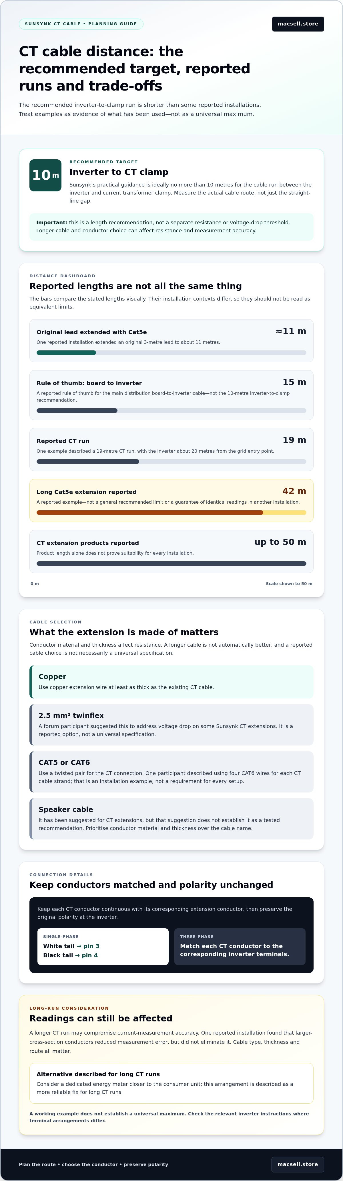
If you’re assessing the Sunsynk CT coil extension cable maximum distance, use 10 metres as the recommended target for the run between the inverter and CT clamp. Longer runs have been reported, including one extended to 42 metres with Cat5e cable, but that example isn’t a general recommended limit. Cable choice matters: use copper at least as thick as the existing CT cable, and a twisted pair if extending with CAT5 or CAT6.
A longer cable is not automatically better. Conductor material and thickness affect resistance, which can influence measurement accuracy, so consider the extension cable as carefully as its length.
It’s reasonable to want a clear maximum before routing cable between a distribution board and inverter. This guide explains the recommended length, compares suitable extension cable materials and thicknesses, and outlines what to consider when a longer CT tail is needed. You’ll have a practical reference for planning the run and understanding the trade-offs.
Key Takeaways
- Separate the recommended CT run from longer lengths reported in use; a working example doesn’t establish a universal maximum.
- Choose extension cable with the conductor size and arrangement in mind, as these can affect measurement accuracy.
- For a long run, weigh the reported extension examples against the potential benefit of locating a dedicated energy meter closer to the consumer unit.
- Use the reference to plan the CT route and identify when the cable distance may call for a different monitoring approach.
Sunsynk's recommended CT cable length
A recommended CT cable run is the distance between the inverter and current transformer clamp. For Sunsynk systems, the practical target is no more than 10 metres.
Inverter Model CT Cable Limits
Model-specific CT cable limits are distance recommendations tied to an inverter’s CT connection. The general Sunsynk guidance places the inverter-to-clamp run at ideally no more than 10 metres, rather than setting separate distances by inverter capacity.
The same 10-metre guidance applies to Sunsynk inverter-to-CT runs generally; it does not identify a list of models sharing a distinct limit. For model-specific wiring, use the relevant inverter instructions, particularly where terminal arrangements differ. Don’t infer a longer CT run from an inverter’s power rating alone.
A 15-metre limit is sometimes cited for the cable between the main distribution board and inverter. That figure is a reported rule of thumb, not the same recommendation as the 10-metre inverter-to-clamp target. Measure the actual cable route, not just the straight-line gap, before deciding whether the CT run falls within the shorter target.
Sunsynk CT coils measure grid import and export current, and the inverter uses those readings to respond to changes in household load. Keep the clamp close to the inverter where practical, and don’t assume a longer cable is automatically within the recommended run.
CT Cable Resistance and Voltage Drop
CT cable resistance is the opposition to current through the cable, whilst voltage drop is the resulting reduction in voltage along its length. Sunsynk’s 10-metre guidance is a cable-length recommendation, not a separate resistance or voltage-drop threshold.
That distinction matters when planning an extension. A longer run adds cable, and conductor material and thickness affect resistance. Use copper extension wire at least as thick as the existing CT cable. The next section explains what to consider when choosing the cable.
For example, if the inverter sits beyond the recommended 10-metre run, don’t judge suitability by distance alone. Consider the conductor and the route together, since measurement error can remain even after extending the cable with larger-cross-section wire. Keep the CT cable route as direct as practical, and avoid assuming that a length reported in another installation guarantees the same measurement behaviour.
Extension cable material and thickness
CT extension cable is the added conductor connecting the CT coil tails to the inverter. Use copper wire at least as thick as the existing CT cable, since the conductor material and cross-section affect resistance along the extended run.
Cross-section is the copper area inside a conductor, measured in square millimetres. A forum participant suggested 2.5 mm² twinflex cable to address voltage drop on some Sunsynk CT extensions. Treat that as a reported option, not a universal specification: the existing CT lead and the extension length both matter.
Twisted pair means two insulated conductors twisted around each other. If using CAT5 or CAT6 cable, use a twisted pair for the CT connection to reduce resistance and help protect the signal from interference. One forum participant described using four CAT6 wires for each CT cable strand. That is an installation example, not a requirement for every setup.
Speaker cable is a flexible paired conductor sometimes suggested for CT extensions. However, a suggested use does not establish it as a tested recommendation. Prioritise copper wire at least as thick as the original conductor rather than choosing by cable name alone.
To extend the tails, keep each CT conductor continuous with its corresponding extension conductor, then preserve the original polarity at the inverter. For a single-phase Sunsynk connection, the white tail goes to pin 3 and the black tail to pin 4. For a three-phase connection, match each CT conductor to the corresponding inverter terminals.
Larger-cross-section wire has reduced measurement error in a reported installation, but did not eliminate it. For wider system planning, browse solar hardware options.
Maximum CT tail extension
A CT tail extension is the added cable between a Sunsynk clamp and inverter. Installations have used runs of different lengths, but a working example does not set a universal limit.
Risks of Excessive CT Cable Extension
Excessive CT cable extension is a run long enough to compromise the accuracy of current measurement. A forum participant reported extending an original 3-metre lead to about 11 metres with Cat5e; another described a 42-metre Cat5e extension. These examples show what has been used, not that every cable and inverter will perform identically.
The main risk is measurement error. One reported installation found that larger-cross-section conductors reduced the error, but not enough to change the setup. A separate example used a 19-metre CT run with the inverter about 20 metres from the grid entry point. Cable type, conductor thickness and route all affect whether a long extension gives reliable readings.
For a long route, compare the intended run with these examples, then consider a dedicated energy meter closer to the consumer unit. That arrangement is described as a more reliable fix for long CT runs. CT coil extension products have also been reported in lengths up to 50 metres, but product length alone does not prove suitability for every installation.
Effects on Readings, Export Control and Warranty
CT measurement accuracy describes how closely the clamp reports grid current to the inverter. Because Sunsynk CT coils measure real-time grid import and export, cable-related error can affect the readings used for control. Inaccurate readings may cause export-control behaviour to differ from the actual current at the grid connection.
Warranty coverage is governed by the applicable product terms; reported cable lengths are not warranty approval. The 11-metre Cat5e and 42-metre Cat5e examples describe reported operation, not a warranty decision. Keep the original cable details and extension arrangement documented, and avoid treating another installation’s result as proof of coverage or performance for yours.
For a planned run beyond the recommended target, weigh the cable route against measurement reliability before extending the tails. The 19-metre example and reported 50-metre extension products illustrate different setups, not a guaranteed maximum. Where the CT measurement is critical to export control, placing a dedicated energy meter nearer the consumer unit offers a more reliable approach than relying on an increasingly long CT cable.
What is the maximum extension cable length for a Sunsynk CT coil?
A CT extension’s maximum length is the longest run that still gives the inverter usable measurements. For Sunsynk, treat 10 metres as the ideal inverter-to-clamp run, not a guaranteed absolute ceiling.
The maximum distance for a Sunsynk CT coil extension cable depends on more than its stated length. Conductor thickness, cable material and the route can all affect measurement accuracy. Longer runs have been used, but those examples do not establish a maximum that applies to every installation.
A 30-metre gap between the main distribution board and planned inverter location illustrates the planning challenge. That distance does not automatically mean the CT tail needs to span 30 metres: plan the clamp and inverter positions around the actual cable route. Keep the CT run as short as the layout allows, then assess any extension against the 10-metre ideal.
A 15-metre figure is also cited as a limit for the cable between the distribution board and inverter. It is a reported rule of thumb, and describes a different measurement from the inverter-to-clamp recommendation. Don’t treat the two distances as interchangeable when mapping the installation.
For a longer run, use these practical steps:
- Measure the intended route between the CT clamp and inverter, including bends and detours.
- Compare that measurement with the 10-metre ideal, rather than relying on the straight-line distance.
- Choose copper extension cable at least as thick as the existing CT lead, and maintain the CT tail polarity.
- If the layout requires a substantially longer run, consider a dedicated energy meter closer to the consumer unit.
A reported 50-metre extension product shows that long extensions exist, not that this length suits every Sunsynk setup. For a 30-metre board-to-inverter layout, prioritise a reliable measurement arrangement over matching the extension to the full separation. Explore solar system components when planning the wider hardware layout.
MacSell Solar Outlet: Sunsynk 8KVA & 2X Hubble AM2 5.5 KWh Combo Kit
MacSell Solar Outlet offers the Sunsynk 8KVA & 2X Hubble AM2 5.5 KWh Combo Kit for readers planning a Sunsynk-based solar system alongside their CT cable layout. The kit brings together inverter and battery hardware; it does not replace the need to plan the CT cable route and connection separately.
If you’re selecting system components, MacSell Solar Outlet offers hybrid inverters, lithium batteries and solar panels. Consider how these products fit your wider system requirements. The CT distance guidance here can inform your layout planning, while the hardware selection supports the broader system build.
Visit macsell.store to explore the available solar hardware.
Plan the next step for your solar system
Use the Sunsynk CT coil extension cable maximum-distance guidance as one part of system planning, not as a substitute for a complete layout. Before choosing equipment, note the positions of the inverter and grid connection, the cable route and what the system needs to support. This gives you a clearer basis for selecting compatible hardware.
MacSell Solar Outlet offers the Sunsynk 8KVA & 2X Hubble AM2 5.5 KWh Combo Kit, alongside lithium batteries and hybrid inverters. These options can help you consider inverter and storage components as part of the wider system, rather than treating the CT cable decision in isolation.
For guidance on the available hardware and your system choices, contact MacSell Solar Outlet for advice. Take your layout plan into the next step with a clearer view of the components you need.
Frequently Asked Questions
What cable type and conductor size does Sunsynk specify for extending a CT coil?
Use copper extension wire at least as thick as the original CT cable; 2.5 mm² twinflex has also been suggested for some extensions. That suggestion is not a universal Sunsynk specification. For example, if the existing tails are thinner, don’t reduce the conductor size in the extension. Cable resistance and the total run affect measurement behaviour, so match the conductor to the existing lead and installation layout.
Can a Sunsynk CT coil cable be extended with twisted-pair or shielded cable?
Yes, twisted-pair CAT5 or CAT6 cable has been used for CT extensions, with a pair assigned to the CT conductors. Twisting helps reduce resistance and interference. Shielding is a separate cable feature, not a replacement for maintaining the correct conductor pairing and polarity. Keep the CT tails identifiable at both ends, then connect them to the inverter’s designated terminals.
What do Sunsynk manuals and technical support say about CT cable extension distance?
Use 10 metres as the ideal inverter-to-CT clamp cable run for practical planning. A separate 15-metre figure is cited for the cable between the main distribution board and inverter, so don’t confuse the two measurements. Longer extensions have been used, but reported examples don’t establish a general maximum or replace model-specific wiring instructions. Measure the route and account for its cable type and conductor size.
Which Sunsynk inverter models use the same CT coil and cable limits?
The same 10-metre ideal inverter-to-CT run applies to Sunsynk inverters generally; no separate limit by inverter capacity is given.