

Hubble AM2 Battery Communication Setup with Sunsynk 8kVA: Step-by-Step Guide (2026)
Could adding another communication device fix a Hubble AM2 and Sunsynk 8kVA pairing, or make troubleshooting harder? The Hubble AM2 battery communication setup with Sunsynk 8kVA usually starts with one direct CAN bus link. A Hubble Cloudlink is an alternative pathway when it suits the system’s communication or monitoring needs, not an extra cable to add by default.
If you’re unsure which battery port to use, how to set the master battery’s DIP switches, or which inverter menu options matter, you’re not alone. A connection can appear complete while the inverter receives no battery data. The connection sequence and model-specific settings both matter.
This guide explains how to choose between direct CAN communication and Cloudlink, then outlines the connection order and checks for confirming that the inverter can read the battery. It also covers common wiring and configuration mistakes. Follow the current manuals for your exact models, and have a qualified electrician carry out electrical installation work.
Key Takeaways
- Choose one communication route: direct CAN bus where the exact equipment configuration supports it, or Cloudlink when it suits the system’s communication needs.
- For the Hubble AM2 battery communication setup with Sunsynk 8kVA, use the current model-specific manuals to verify ports, cable details, DIP-switch positions and inverter settings.
- Follow an ordered setup: identify the equipment, select the route, connect the communication link, configure the system and verify that battery data reaches the inverter.
- In a multi-battery configuration, identify the master and slave roles and check that the battery-link connections match the applicable manual.
- See how the communication pathway relates to the Sunsynk 8KVA and 2X Hubble AM2 5.5 KWh Combo Kit.
What Hubble AM2 and Sunsynk 8kVA communication setup needs to achieve
The communication link lets the Hubble AM2 battery management system (BMS) exchange battery data with the Sunsynk inverter. This is separate from the DC power cables that carry energy between the battery and inverter. A communication cable does not replace power wiring, determine system sizing or complete an installation.
BMS communication exchanges battery status and management information between the battery and inverter, so the inverter can respond to the battery’s reported condition and charge limits. In a correctly configured system, this information helps the inverter interpret battery status and operate within the parameters communicated by the BMS. A plugged-in cable is not proof that data is reaching the inverter. The protocol, ports and settings must also match.
What information travels between the battery and inverter?
The BMS monitors the battery and shares relevant data through the communication interface. Depending on the protocol and equipment configuration, this can include State of Charge (SOC), battery condition, charge or discharge limits and fault status. The inverter uses compatible BMS data to inform its battery-control behaviour. Missing or implausible readings can indicate that the communication path needs checking.
For this pairing, CAN bus is the standard direct communication route described for the AM2 and Sunsynk 8kVA. CAN carries BMS data, not energy. The CAN bus communication protocol is a data network used to exchange messages between connected devices. RS485 is a separate interface; depending on the equipment and setup, it may serve monitoring or other communication functions. Don’t treat an RS485 port as interchangeable with CAN, or assume its role from the connector shape. Check the port labels and instructions in the relevant manuals.
What to identify before connecting the AM2
Start by recording the precise equipment details. The Sunsynk 8kVA description alone may not identify the inverter revision or its communication-port layout. Confirm the full model information and inspect the unit’s labelled ports using the current manual. Port layouts and menu wording can vary, so don’t rely on directions written for a different revision.
- Inverter: Record the exact model and identify its designated battery communication port and supported protocol.
- Battery: Identify the Hubble AM2 revision and consult its current setup documentation for compatible communication instructions.
- Battery count: Establish whether the system has one AM2 or multiple batteries. Master and slave roles apply to relevant multi-battery configurations, not automatically to a single battery.
This preparation gives the Hubble AM2 battery communication setup with Sunsynk 8kVA a clear starting point: match the actual equipment and manuals before selecting ports or settings. Keep communication configuration separate from power cabling and system design. A qualified electrician should handle electrical connections and installation work.
Prepare the Hubble AM2 master battery and Sunsynk communication ports
Prepare the equipment before connecting anything. The Hubble AM2 battery communication setup with Sunsynk 8kVA depends on matching instructions to the actual battery and inverter revisions. Don’t copy a DIP-switch example or cable diagram simply because it names an AM2 or an 8kW Sunsynk. Manuals and port layouts can differ between models.
Use this order to organise the checks. Electrical isolation and installation work must be handled by a qualified professional. Battery and inverter equipment can present hazardous electrical risks. Communication preparation is not permission to work on live wiring. At this stage, identify the equipment and check the documentation rather than making unverified electrical changes.
- Identify the equipment. Record the full Sunsynk inverter model and revision, and the Hubble AM2 model or revision shown on the equipment labels.
- Find the current manuals. Use the matching Sunsynk and Hubble documentation. Locate the communication diagram, port labels, DIP-switch instructions and any battery-link requirements.
- Count the batteries. Establish whether the system has one AM2 or a multi-battery bank. Master and slave roles apply only when the supported configuration uses multiple batteries.
- Map the ports. Match the manual diagrams to the labels on the actual inverter and batteries. Identify the ports for inverter BMS communication, battery-to-battery links and monitoring.
- Confirm the cable specification. Check the required cable type and pin layout in the current model-specific documentation before connecting it.
Set the AM2 battery roles and addresses
In a supported multi-battery bank, the master coordinates communication with the inverter, while additional batteries connect according to Hubble’s instructions. The manual determines which battery has each role and how unique addresses are set. Check the DIP-switch table for the exact AM2 revision, because switch positions shown for another example aren’t universal. Fit inter-battery link cables only where the AM2 instructions require them, using the specified sequence and ports.
For a single-battery setup, don’t apply multi-battery addressing steps by default. Use the single-battery configuration in the relevant manual. If the prescribed roles, addresses or link arrangement aren’t clear, pause rather than guessing.
Identify the correct Sunsynk port and cable path
Sunsynk 8kVA inverter port layouts can vary. Use the diagram for the exact unit to distinguish its BMS communication port from RS485, monitoring or other connections. A battery-link port serves a different purpose from the inverter-facing communication port. Connector shape alone doesn’t establish compatibility.
Don’t assume RJ45 pin assignments are standard across equipment. Verify the required pinout and cable path in the current Sunsynk and Hubble documentation, then match each end to its labelled port. Correct port identification and cable routing are essential, even though the communication cable carries data rather than battery power.
Once the model, roles, ports and cable requirements are clear, the setup is ready for configuration. For the listed Sunsynk and dual-AM2 hardware combination, see the Sunsynk and Hubble hardware option.
Direct CAN bus or Cloudlink: which Hubble AM2 communication route fits?
Choose the communication route before connecting cables. For a supported Hubble AM2 and Sunsynk 8kVA configuration, direct CAN is the simpler pathway: the correctly configured master battery communicates with the inverter. A Hubble Cloudlink is an alternative that can act as a CAN bus converter and provide cloud monitoring. It requires its own connections and setup, so it isn’t an extra CAN source to connect alongside the battery.
The key rule is simple: select one BMS-to-inverter CAN pathway. Don’t connect both the AM2’s CAN output and the Cloudlink’s CAN output to the inverter at the same time. Use the current manuals for the exact inverter and battery revisions to confirm compatible ports, cable details and settings.
| Route | Required hardware and connection path | Purpose |
|---|---|---|
| Direct CAN | Communication cable from the master AM2 CAN port to the Sunsynk BMS CAN port, subject to the manuals. | Direct BMS communication between the battery bank and inverter. |
| Cloudlink | Cloudlink connects to the battery through the specified serial connection and to the inverter through CAN. An RS485 link may be used for inverter monitoring where the instructions specify it. | Provides a converted CAN communication route and cloud monitoring. |
When direct battery CAN is the appropriate route
Use direct CAN when the exact AM2 and Sunsynk configuration supports the connection described in their manuals. In a multi-battery bank, configure the master first; its CAN port is the inverter-facing connection. Follow the manual for battery-link wiring and address settings. This route sends BMS data directly to the inverter and doesn’t require a Cloudlink for that communication path.
Keep the cable path clear: connect the master battery CAN port to the inverter’s designated BMS CAN port, without connecting a Cloudlink CAN output to the same BMS pathway. Verify the port labels and pinout for the actual equipment rather than relying on the cable’s appearance.
When the Cloudlink route is being used
Choose Cloudlink when its conversion or monitoring functions are needed for the system. In this route, the battery’s specified serial connection feeds the Cloudlink, and the Cloudlink’s CAN connection feeds the inverter’s BMS CAN port. An inverter RS485 connection is separate and may support monitoring when the relevant instructions call for it.
Set Cloudlink options according to the current documentation for the exact inverter and battery configuration. Examples in Hubble materials aren’t universal defaults. Before power-up, confirm that the direct battery CAN lead isn’t also connected to the inverter. Two CAN sources on one BMS pathway can disrupt communication rather than improve it.
In short, direct CAN is the straightforward choice when supported; Cloudlink is a distinct alternative. Connect only the selected pathway, then move on to configuration and verification.
Configure and test the Hubble AM2 with Sunsynk 8kVA step by step
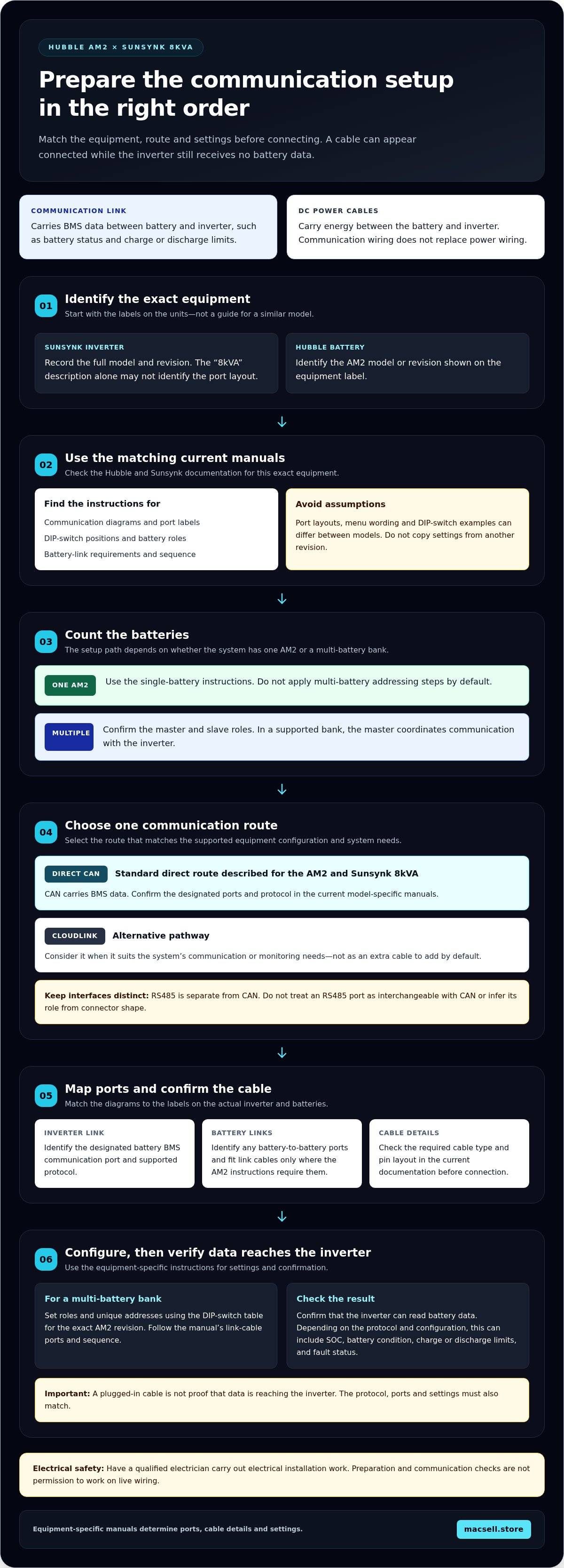
Use a fixed sequence: confirm the manuals, select one communication route, connect the equipment, configure the relevant settings, then verify the inverter’s battery status. Keeping wiring checks separate from menu changes makes faults easier to isolate. Electrical work and equipment isolation should be handled by a qualified professional.
Settings must match the exact battery revision, inverter model and firmware, and selected communication route. Incompatible values can prevent accurate BMS communication. Use current Hubble and Sunsynk documentation for the specific equipment. Treat published AM2 or Cloudlink settings as reference examples, not defaults to copy.
- Confirm the manuals. Match each document to the model and revision labels on the AM2 and Sunsynk inverter. Find the communication diagram, compatible battery type, charge-setting guidance and relevant setup menus.
- Choose one route. Decide between direct CAN from the configured master battery or the Cloudlink pathway. Don’t connect both CAN sources to the inverter’s BMS communication path.
- Connect the selected route. Follow the manufacturer’s port diagram and specified cable details. For a multi-battery bank, confirm the master configuration and required battery links before connecting the inverter-facing communication cable.
- Configure the equipment. Use the inverter’s battery-type and charge-setting menus identified in its manual. Apply the corresponding Hubble communication guidance. For Cloudlink, check its settings against the current Hubble instructions and the selected inverter connection.
- Verify status. Check the inverter display or monitoring interface for battery communication and plausible battery data before treating setup as complete.
Apply battery and inverter settings safely
Menu names and locations depend on the Sunsynk model and firmware. Find the battery type, BMS protocol and charge-related settings in the inverter manual, then compare them with Hubble’s instructions for the AM2 revision. Don’t apply example values automatically. Confirm each setting against current documentation for the exact system. This guide doesn’t prescribe charge limits or shutdown thresholds; use only the manufacturer’s model-specific guidance.
Confirm communication and diagnose common faults
Start by checking the physical route. For direct CAN, confirm that the cable runs from the configured master AM2 CAN port to the correct Sunsynk BMS CAN port. For Cloudlink, check the battery serial connection and inverter CAN connection separately. Check an inverter RS485 link only where the Cloudlink instructions specify it.
- Compare the cable pin layout with the current manual. A familiar connector shape doesn’t confirm that the wiring is correct.
- Confirm that the cable is in the designated communication port at both ends, not a battery-link or monitoring port.
- Check that only the selected CAN pathway reaches the inverter. Remove any duplicate CAN connection before changing settings.
- If communication is still absent or readings appear inconsistent, compare the displayed status with the manual and review model compatibility and firmware guidance before altering values.
For a hardware option that pairs these components, explore the Sunsynk 8KVA and 2X Hubble AM2 5.5 KWh Combo Kit.
Choose the right hardware combination for an AM2 and Sunsynk 8kVA setup
Choose hardware by separating three questions: does the battery capacity suit the system design, does the inverter meet the system’s performance needs, and can the exact equipment communicate correctly? These checks are related, but none answers the others. A compatible communication route doesn’t establish that the system is correctly sized or that every required component is included.
The communication connections depend on the route selected. With direct CAN, the configured master AM2 connects to the designated Sunsynk BMS CAN port, following the relevant manuals. With Cloudlink, the battery and inverter connections follow the Cloudlink pathway instead. In either case, use one BMS-to-inverter CAN route and confirm the port layout and cable requirements for the actual model revisions.
Check the combination against the system design
Before choosing the communication connection, confirm the exact inverter model, number of AM2 batteries and intended route against current product documentation. For a multi-battery arrangement, check the battery-bank instructions for master configuration, addressing and required links. Assess capacity and inverter performance against the system’s needs as separate design tasks. Communication compatibility alone doesn’t confirm that the system design is suitable.
Keep the kit contents distinct from the wider system. The listed combination is the Sunsynk 8KVA and 2X Hubble AM2 5.5 KWh Combo Kit. Don’t assume its name specifies other components, cabling or installation work. The article Sunsynk 8KVA and Hubble AM2 Combo Kit: Technical Review and Hardware Guide (2026) covers the combination from a product-review perspective.
Review the listed Sunsynk and Hubble combo kit
The combo kit brings together a Sunsynk 8KVA inverter and two Hubble AM2 5.5 KWh batteries. It provides a clearly identified starting point for checking the system design and selecting the communication route. You’ll still need to follow the manuals for the exact equipment revisions, configure the battery bank correctly and verify inverter communication after setup.
For the Hubble AM2 battery communication setup with Sunsynk 8kVA, make your connection plan from the chosen route rather than adding both direct battery CAN and Cloudlink CAN connections. Check equipment identity, battery count, ports, settings and status separately. This keeps the hardware choice tied to the actual communication pathway and system requirements.
View the Sunsynk 8KVA and 2X Hubble AM2 combo kit.
Move from setup plan to a verified system
Turn your setup plan into a clear system record before routine operation. Note the inverter and battery revisions, selected communication route, manual versions consulted, settings applied and status shown during verification. This gives you a useful baseline for future checks and helps distinguish a new fault from an earlier configuration issue.
Keep the record with the system documentation. If readings remain inconsistent, avoid cycling through unrelated menu changes. Pause and compare the configuration with current manufacturer instructions. Have a qualified electrician assess electrical work or unresolved safety concerns. A documented baseline is more useful than a collection of guessed settings.
The Hubble AM2 battery communication setup with Sunsynk 8kVA is model-specific, not a one-size-fits-all recipe. Verify the exact hardware combination and communication pathway before making changes. View the Sunsynk 8KVA and 2X Hubble AM2 combo kit and plan your setup around the equipment and its manuals.
Frequently Asked Questions
Can a Hubble AM2 communicate directly with a Sunsynk 8kVA without Cloudlink?
Yes, direct communication is possible where the exact Hubble AM2 and Sunsynk configuration supports it. Hubble documentation describes a CAN connection from the configured master battery to the inverter. Cloudlink is an alternative pathway, not an automatic requirement. For the Hubble AM2 battery communication setup with Sunsynk 8kVA, use the current manuals to confirm ports and settings. Don’t connect the battery CAN and Cloudlink CAN to the inverter simultaneously.
Do I need Cloudlink for a Hubble AM2 and Sunsynk inverter?
No, Cloudlink isn’t mandatory for every supported setup. Manufacturer material describes both direct battery CAN communication and a Cloudlink-based route. Cloudlink adds a battery serial connection and can use RS485 for inverter data collection, depending on the system instructions. That monitoring connection has a different role from the CAN pathway carrying BMS communication to the inverter. Choose the route supported by your equipment and follow its connection diagram.
What does it mean if the Sunsynk does not detect the Hubble AM2?
It means the inverter isn’t receiving or recognising the expected battery communication data, but that alone doesn’t identify the cause. Check the selected route first, then the master-battery configuration, inverter port and cable routing against the manuals. If using Cloudlink, inspect its battery serial and inverter connections separately. Cable or port errors can interrupt communication. Don’t change charge or protection settings by guesswork; use qualified assistance for electrical work.
Can two Hubble AM2 batteries connect to one Sunsynk 8kVA?
Yes, the listed MacSell Solar Outlet combo kit pairs a Sunsynk 8KVA with two Hubble AM2 batteries. For a multi-battery bank, follow the applicable Hubble instructions for assigning the master and additional batteries, addressing and any required battery links. DIP-switch positions depend on the AM2 revision. Don’t copy a switch setting from a single-battery example or another model; use the current documentation for the batteries in your system.
Should the battery CAN cable and Cloudlink CAN cable both connect to the inverter?
No. Use one CAN source for the inverter’s BMS communication path. Connecting both the battery’s CAN output and Cloudlink’s CAN output to the inverter at once can cause communication problems. If using Cloudlink, keep its battery serial connection and any specified RS485 monitoring connection distinct from its inverter CAN link. Before powering up, check the selected route against the equipment diagrams and remove any duplicate CAN connection.
Are Hubble AM2 voltage and current settings the same for every Sunsynk 8kVA?
Don’t assume one settings table applies to every pairing. Hubble-published AM2 values are examples that need checking against the current battery documentation, exact Sunsynk model and system configuration. Hardware or firmware revisions may also affect menu labels and supported options. Find the relevant battery and inverter settings in their manuals, and apply only values that match those instructions. Avoid copying charge limits or shutdown thresholds from an unrelated setup.
What is the difference between CAN bus and RS485 in a Hubble Cloudlink setup?
CAN carries the battery-management communication between the battery pathway and inverter. In a Cloudlink setup, RS485 may provide a separate connection for collecting inverter data for the Cloudlink portal, where the instructions specify it. RS485 isn’t a substitute for the BMS CAN connection. Port labels and cable arrangements vary by equipment, so use the applicable Hubble and Sunsynk diagrams to identify each connection before setup.