

LuxPower SNA5000 Parallel Set-up: 2026 Hardware Guide
What if the inverters are connected, but the hardware still isn’t ready for parallel operation? The LuxPower SNA5000 parallel connection setup hardware involves more than a set of cables: the exact inverter model and revision, communication links and power connections all need to match the applicable model-specific documentation. Instructions for a different version can lead to the wrong cable, connection sequence or setting.
Before planning connections, confirm that each unit is the parallel-capable model specified for the system. Then use the documentation for that hardware revision to check the required components, cable types, connection sequence and settings. This guide explains the role of each component and provides a practical checklist for compatibility, physical connections and communication checks. It also shows how to keep parallel communications, battery wiring and monitoring separate in your component plan. Use the checks to identify gaps before configuration and commissioning, rather than assuming that instructions for another SNA5000 version apply.
Key Takeaways
- Use the LuxPower SNA5000 parallel connection setup hardware guide to distinguish communications links, power conductors and battery interface wiring.
- Confirm the inverter model, hardware revision and supported topology before selecting components or planning connections.
- Check physical links, inverter settings, portal monitoring and operating status as separate verification steps.
- Follow a pre-commissioning sequence that checks documentation, connections and settings before commissioning work proceeds.
- Assess battery, PV and protection requirements for the complete system; adding parallel inverters doesn’t replace appropriate system sizing.
What a LuxPower SNA5000 parallel connection changes in a solar system
Installing multiple inverters doesn’t, by itself, create a parallel system. Parallel operation requires the units to coordinate using the connections and configuration specified for the relevant inverter model. Placing two units at the same site or connecting them to the same battery bank doesn’t establish that coordination.
Quotable definition: “Parallel operation is the coordinated operation of multiple inverters through the connections and settings specified by the manufacturer for the exact model and system topology.” Treat this as a general description, not a wiring instruction. The applicable LuxPower documentation determines how parallel operation is set up for the specific SNA5000 model and hardware revision.
A solar inverter converts electrical power from DC to AC. In a parallel arrangement, the inverters are intended to coordinate their system operation rather than act as unrelated devices. That distinction affects component selection and the connection plan.
What parallel operation is intended to coordinate
Inverter-to-inverter communication supports coordination between the units. It is separate from the battery interface: where used, battery communication carries information between an inverter and a compatible battery management system. Monitoring connectivity is another function, providing access to system information through the relevant platform. These links may serve different purposes, so don’t assume one connection replaces another.
The system-level aim is coordinated operation, but the details depend on the instructions for the exact configuration. Don’t infer a particular power-sharing behaviour, operating mode or capacity increase from the word “parallel” alone. Adding a second inverter also doesn’t automatically increase what the battery bank, PV array, conductors or grid-side equipment can support. Each part of the system has its own ratings and compatibility requirements.
Why the exact SNA5000 configuration matters
Start with the inverter’s identification label. Record the model designation and hardware revision, then match them to the applicable manual and parallel-connection instructions. Similar product names don’t prove that units share the same parallel capability, connection points or supported configuration.
Before choosing a connection plan, verify these details in the manufacturer documentation for the exact hardware:
- Model and revision: Confirm that the specific unit is designated for the intended parallel application.
- Topology: Check whether the documented arrangement matches the planned system, such as a single-phase configuration. Don’t apply instructions for a different topology by assumption.
- Supported unit count: Confirm the permitted number of units and any restrictions for that arrangement.
- Connection and configuration details: Check the specified communication links, settings and verification method. Don’t rely on a cable, switch position or portal instruction copied from another model.
This is the basis of the LuxPower SNA5000 parallel connection setup hardware decision: establish which exact units and topology are supported before treating a general diagram or an example from another setup as applicable.
LuxPower SNA5000 parallel setup hardware: what each connection does
A parallel system involves more than matching inverter units. The hardware plan needs to account for the inverter-to-inverter communication link, battery connections, AC and DC power conductors, and the protection specified for the complete system. Each has a different job. Treating one cable or connection as a substitute for another can leave an important component out of the plan.
For the LuxPower SNA5000 parallel connection setup hardware, use the documentation for the exact model and hardware revision to identify approved components and connection points. The overview below explains what to look for without assuming a cable type, cable count, rating or setting that may not apply to your unit.
Parallel communications cable and inverter ports
Start at the inverter. Locate the communication-port labels on the exact unit and compare them with the matching manufacturer diagram. A connector’s shape alone doesn’t establish its pinout, purpose or suitability. Visually similar ports can serve different functions.
Before selecting or connecting a lead, verify the documented cable type, number of links, port sequence and any termination requirements. These details can vary by model or configuration. Don’t assume a standard network cable will work just because the port resembles an Ethernet socket. The smart inverters overview provides broader context on inverter capabilities, but LuxPower’s SNA5000 documentation is the source for its connection instructions.
Battery, AC and protection hardware
Battery communication is distinct from the parallel link between inverters. Where the chosen battery and system design use BMS communication, that wiring serves the battery-to-inverter interface. It doesn’t perform the same function as inverter-to-inverter communications or monitoring connectivity.
Power conductors carry energy, whilst protective devices form part of the electrical design. Their specifications depend on the approved configuration and applicable equipment requirements. Don’t select breaker, fuse, cable or busbar ratings by copying a diagram for a different setup. Confirm the relevant ratings and arrangement in the applicable documentation and system design.
- Parallel communications: Check the inverter communication ports, link requirements and sequence in the model-specific instructions.
- Battery interface: Match communication wiring and power connections to the battery and inverter documentation.
- AC and DC power paths: Confirm conductor and protection requirements against the approved system design.
- Monitoring: Treat monitoring connections and platform access as separate from the physical parallel link.
DIP switches and configuration-dependent hardware
Don’t assume DIP switches are present, required or set in a particular way on every SNA5000 revision. If the applicable manual specifies hardware addressing or switch positions, follow the instructions for that exact configuration. Forum examples may describe one installation, but they don’t establish a universal setting.
Keep physical switch positions separate from inverter software settings and portal configuration. Record each requirement against its source before preparing the component list. For a wider view of the equipment, browse MacSell Solar Outlet's solar hardware range.
SNA5000 parallel connection: separate confirmed hardware from setup assumptions
Parallel setup questions often combine four separate checks: the physical communication link, inverter configuration, portal monitoring and evidence of operating status. Keep them distinct. A connected cable doesn’t prove the units are configured correctly, and a portal displaying system data doesn’t, on its own, verify local inverter-to-inverter communication. For the LuxPower SNA5000 parallel connection setup hardware, use the documentation for the exact model and hardware revision to check each requirement.
| Setup question | What it affects | Official source to verify |
|---|---|---|
| Are the communication ports and link arranged as specified? | Physical connection between inverter units. | Current parallel-connection instructions for the exact SNA5000 model and revision. |
| Which inverter settings apply? | How the units are configured to operate together. | Applicable SNA5000 user or installation documentation. |
| Is portal access required for setup? | Monitoring or any portal-dependent configuration steps. | Current LuxPower instructions covering the model and portal function. |
| What status confirms operation? | How communication or faults are indicated and interpreted. | Display, status and alarm definitions for the exact revision. |
| Which phase arrangement and unit count are supported? | Permitted system topology and configuration. | Current SNA5000 parallel documentation for the intended topology. |
Single-phase and other supported topologies
Don’t assume that a topology described for another LuxPower model applies to the SNA5000. Phase arrangement and supported unit count depend on the configuration. Confirm both in the SNA5000 documentation before selecting components or following a connection diagram. Use only an arrangement covered by the applicable instructions; don’t extrapolate from a different setup.
Local communication versus portal monitoring
The inverter-to-inverter link is a local communications connection. Portal monitoring is a separate function that may display information remotely. Whether portal setup is required depends on the applicable SNA5000 instructions and the portal function involved. Check those instructions, and don’t treat portal visibility as a substitute for documented local communication and commissioning checks.
Interpreting display indicators and alarms
Use only status indicators, messages and alarm definitions documented for the exact SNA5000 revision. An inverter showing no warning or error doesn’t necessarily prove that parallel communication is active. Check the documented verification method and interpret display behaviour against the manufacturer’s definitions, not a forum description or an assumption based on another model.
These distinctions also help when comparing inverter options. A broader hybrid inverter hardware buying guide can provide selection context, but the SNA5000’s supported topology and connection requirements still need to come from its own documentation.
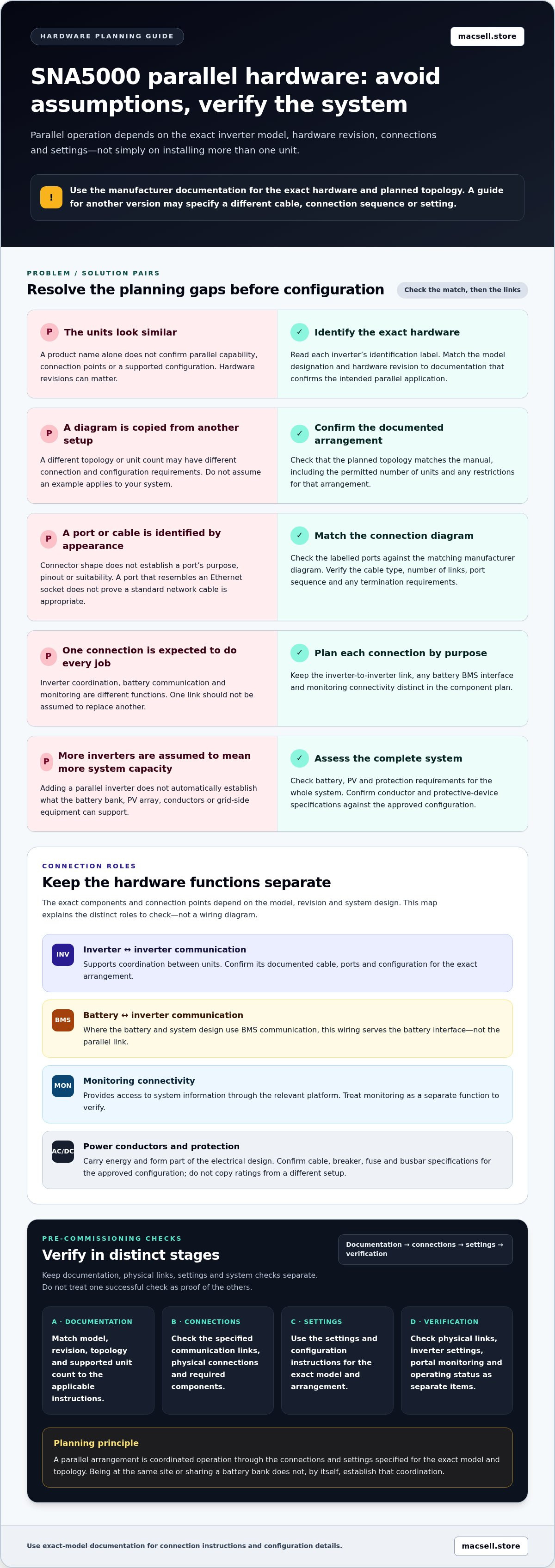
Pre-commissioning checklist for LuxPower SNA5000 parallel hardware
Use this sequence to organise checks before configuration and commissioning. It isn’t a wiring or energisation procedure. Electrical isolation, connection work and commissioning must follow applicable professional safety procedures. Take every pass/fail criterion and energisation step from the manufacturer documentation for the exact SNA5000 model and revision.
- Confirm each inverter. Record the model designation and hardware revision from every unit’s label. Check that the units are approved for the intended parallel arrangement. Don’t infer compatibility from a similar product name or enclosure.
- Match the documentation. Locate the manufacturer instructions that cover those exact units. Check the documented topology, permitted unit count and system-component requirements. Record the manual version used, and stop if the instructions don’t match the equipment or planned arrangement.
- Inspect connection identification. Compare cable labels, port names and connection order with the relevant diagrams. Check that each connection is identified for its intended function. Don’t rely on connector appearance alone or substitute an assumed cable or sequence.
- Verify documented settings. Record each setting specified by the manufacturer and the inverter role it applies to, where roles are defined. Keep physical switch positions, inverter settings and any portal configuration as separate checks. Don’t copy settings from a different revision or an informal example.
- Review status before proceeding. Use only the manufacturer-defined indicators, alarms or commissioning checks for the exact configuration. Compare observed readings with the manual’s pass/fail criteria. Do not energise outputs until the applicable documented checks have passed.
Before connecting or energising equipment
Complete the model, revision and documentation checks before connection work begins. The parallel guide should match the units and topology, and the component plan should remain within its stated limits. Connection labels and port order must also align with the applicable manual. If the equipment, diagram or labels don’t agree, pause rather than resolving the mismatch by assumption.
Configuration and communication checks
Use the manufacturer’s verification method to assess local inverter-to-inverter communication. Portal visibility is a separate check: a system appearing online doesn’t, on its own, demonstrate that the inverters are communicating with each other as intended. Keep a record of the documented settings and status results, including any specified unit roles.
An error-free display alone doesn’t prove that parallel communication is active. Confirm operation through the status indications or commissioning checks defined for the exact SNA5000 version. If the applicable documentation doesn’t define a result clearly, don’t treat an absence of alarms as a pass.
Stop conditions and handover records
Stop if documentation, wiring labels, settings or status readings conflict. Keep a handover record of each inverter’s model and revision, the manual version used, any firmware reference shown in the documentation, confirmed settings and verification results. This gives future troubleshooting a reliable reference without turning assumptions into system history.
For hardware selection, compare the LuxPower SNA5000 inverter hardware with the model and revision details in your system plan.
Choosing LuxPower SNA5000 hardware for a parallel system
Make the system design the starting point for hardware selection, not the number of inverters you hope to use. Before choosing units or accessories, match the intended phase arrangement and load requirements to the SNA5000 documentation. Confirm that the exact model and hardware revision support the planned configuration, then use the relevant manual to establish the permitted unit count and communication requirements.
Parallel inverters don’t automatically increase the capability of every connected component. Battery capacity and compatibility, PV input limits, conductors and protection still need to suit the complete system design. For battery planning, compare the selected battery’s specifications with its manufacturer documentation and the inverter requirements. Lithium-ion chemistry alone doesn’t establish compatibility.
Match the inverter to the documented system design
Check three points before selecting components: the topology supported by the exact SNA5000 revision, the system’s expected loads, and the compatibility requirements for batteries and PV equipment. Keep each check tied to the relevant manufacturer documentation. Battery information is useful when comparing storage options, but it doesn’t replace model-specific compatibility checks for the inverter and battery combination.
MacSell Solar Outlet sells the LuxPower 5kW Inverter - SNA5000 Hybrid Inverter as a solar hardware option. Its role in a parallel system depends on the exact unit and documented system design, so don’t infer parallel capability from the product name alone.
What to include in the hardware plan
Build the component list around confirmed requirements. Separate required connections from optional monitoring functions, and record quantities or ratings only when the applicable documentation specifies them. This keeps the shopping list useful without treating assumed cable types, switch positions or protection ratings as universal.
- Inverter units: Record the exact model designation and hardware revision required for the supported topology.
- Parallel communications: List the approved communication hardware and connection arrangement stated in the applicable instructions.
- Battery interface: Include the required battery power and communication components, based on compatibility documentation.
- PV and AC equipment: Set out the conductors and protection components according to the approved system design.
- Monitoring: Identify portal or monitoring equipment separately, and distinguish it from hardware required for local inverter communication.
Next steps for selecting the SNA5000
Before finalising the hardware plan, confirm the inverter revision, topology, supported unit count, communication requirements, battery and PV compatibility, and protection design. If any detail conflicts with the manual or equipment labels, pause the selection and resolve the mismatch using the applicable manufacturer documentation.
Use this checklist to compare components before choosing the SNA5000. Explore the LuxPower 5kW Inverter - SNA5000 Hybrid Inverter from MacSell Solar Outlet as part of your solar hardware selection.
Turn your system plan into a verified hardware selection
Before moving from planning to purchase, turn the intended system design into a component schedule grounded in model-specific documentation. Keep the exact inverter revision, supported topology and required connections visible in your notes. That gives you a clear basis for comparing the LuxPower SNA5000 parallel connection setup hardware with the needs of your battery, PV array and protection design.
Use the checklist as a decision tool, not a substitute for the manufacturer’s instructions or professional safety procedures. Resolve any uncertain component or requirement against the applicable documentation before treating the hardware plan as complete.
MacSell Solar Outlet sells the LuxPower 5kW Inverter - SNA5000 Hybrid Inverter alongside solar inverters, lithium batteries and related system hardware. View the LuxPower 5kW SNA5000 hybrid inverter as you refine your equipment selection. With the right references and a well-checked plan, you can take the next step with greater clarity.
Frequently Asked Questions
Can two LuxPower SNA5000 inverters be connected in parallel?
Yes, if both units are the parallel-capable SNA5000 variant and the planned arrangement is supported by LuxPower documentation. The SNA5000 name alone isn’t enough to establish this, as model versions can differ. Before selecting a second inverter, compare its label and hardware revision with the applicable manual, then verify that the intended phase arrangement and unit count are supported for that exact configuration.
What hardware is needed for a LuxPower SNA5000 parallel connection?
The hardware plan may include compatible parallel-capable inverter units, the manufacturer-specified communication links, battery connections, AC and PV conductors, and system protection. The exact components and ratings depend on the inverter revision and system design. Treat communications wiring, battery-interface wiring and power conductors as separate items in your component schedule. Use LuxPower and relevant component documentation to determine approved types and quantities, rather than relying on a generic kit list.
How many communication cables are required between parallel SNA5000 inverters?
The required cable count depends on the documented arrangement for the exact SNA5000 version. Don’t choose a number from a forum post or infer it from the ports’ appearance. Check the manufacturer’s connection diagram for the required links, cable type, port sequence and any termination details. If the applicable diagram doesn’t clearly identify the arrangement, pause the hardware selection until you have the correct manual.
Do LuxPower SNA5000 inverters need portal configuration for parallel operation?
Portal access and local inverter-to-inverter communication are separate functions. Whether portal configuration is mandatory depends on the SNA5000 version and arrangement. Follow the current LuxPower instructions for the specific model and revision to determine whether a portal step is required and what it does. A system appearing in an online monitoring view isn’t proof that the local parallel link is operating correctly.
How can I tell whether two LuxPower SNA5000 inverters are communicating?
Use the manufacturer’s documented verification method for the exact hardware revision. This may involve checking specified status indications or commissioning results, but don’t assume the LCD has a particular master, slave or communication indicator. An error-free display alone doesn’t confirm that the units are exchanging data. Compare the observed status with the manual’s definitions, and record the result rather than relying on an informal interpretation.
Can parallel SNA5000 inverters share the same battery?
That depends on the supported system design, battery compatibility and the manufacturer’s connection instructions. Don’t assume that a battery can be shared simply because both inverters support battery operation individually. Check whether the documentation for the exact inverter configuration permits the intended battery arrangement, and compare the battery manufacturer’s connection and communication requirements. The battery’s capacity and limits must also suit the combined system design.
What should I check before commissioning a LuxPower SNA5000 parallel system?
Confirm the model and hardware revision of each inverter, then match them to current documentation for the intended topology and unit count. Check the specified communication arrangement, battery and PV compatibility, protection design, and configuration settings. Ensure the documented status checks and pass criteria are understood before commissioning proceeds. Electrical isolation, connection work and energisation must follow applicable professional safety procedures and the manufacturer’s instructions.