

Hubble AM2 DIP Switch Settings: Sunsynk CAN 2026 Guide
What if the DIP switches are correct, but the battery still isn’t communicating with your Sunsynk inverter? The Hubble AM2 dip switch settings for Sunsynk inverter CAN communication depend on the battery configuration, so a setting copied from an online post may not match your hardware or firmware.
If the inverter doesn’t detect the battery or display its data, changing switches at random can make diagnosis harder. A single-battery setup uses Address 1, but check the exact switch positions in the current Hubble AM-2 manual for your battery revision and configuration before making changes.
This guide provides an ordered way to check battery addressing, the CAN cable and Sunsynk settings against the relevant manuals. It also explains which inverter firmware details and system observations to record when investigating a persistent fault. CAN communication depends on the full setup, not the DIP switches alone. The same checks can help when reviewing equipment such as the Sunsynk and Hubble combo kit, but no single configuration suits every installation.
Key Takeaways
- A working battery power connection doesn’t, by itself, confirm that CAN data is reaching the inverter.
- Use the Hubble AM2 dip switch settings for Sunsynk inverter CAN communication only after matching the battery configuration to the correct manual revision.
- Compare battery addressing, the documented cable path and Sunsynk protocol settings to narrow down likely communication faults.
- Follow an ordered check, record hardware and firmware details, and use the manufacturers’ shutdown instructions before changing settings.
- Use a stop-and-review checklist to make persistent faults easier to diagnose without repeated, unrecorded DIP switch changes.
Hubble AM2 and Sunsynk CAN communication: identify the issue before changing settings
CAN is the communication link that allows a battery’s management system, or BMS, to exchange operating data with an inverter. Depending on the equipment and protocol, this can include state of charge (SOC), voltage, current and battery limits. The Controller Area Network (CAN bus) communication protocol is used in several fields, including industrial systems. In a solar installation, a working battery power connection does not prove that this separate data link is active.
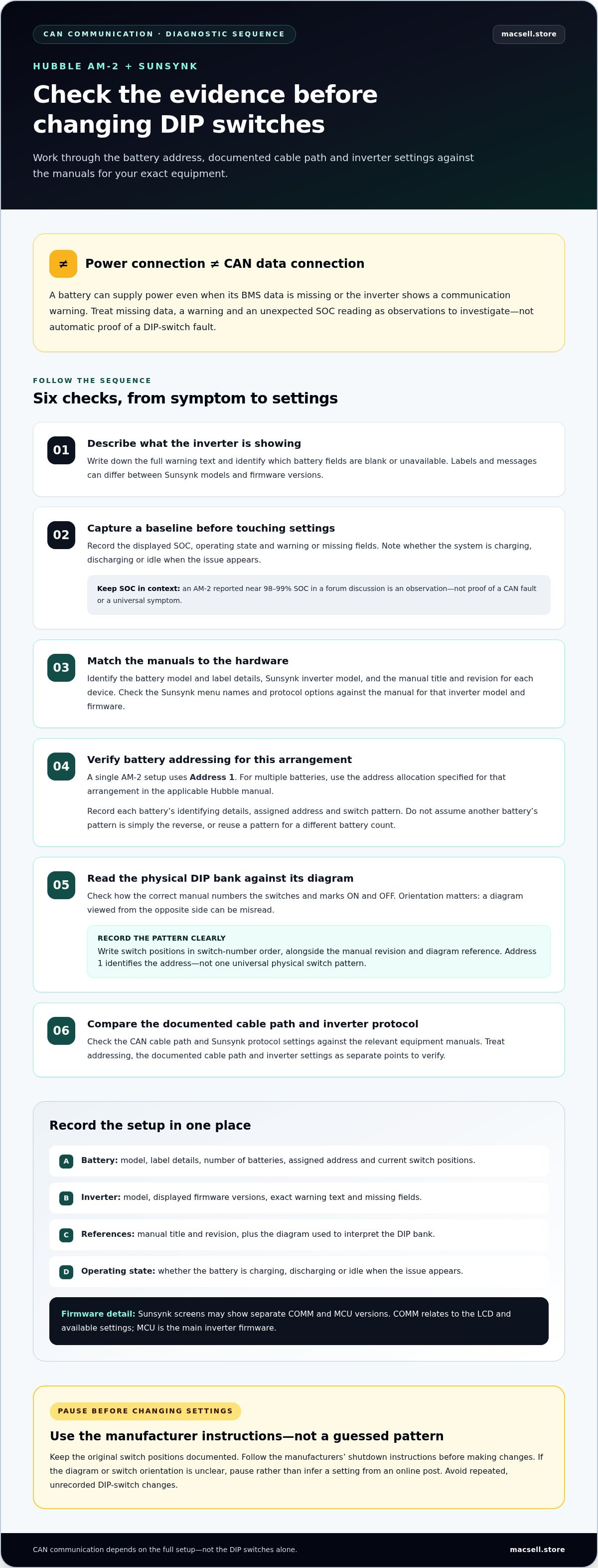
Start by noting exactly what the inverter reports. A battery may supply power even when its BMS data is missing or a communication warning is displayed. That calls for different checks from an SOC reading that seems unusual. Don’t change DIP switches just because a battery’s displayed charge appears to stall or differ from your expectations.
What does a CAN communication fault look like?
Depending on the inverter model and firmware, signs may include missing battery information, blank or unavailable data fields, or a communication warning on the display. Record the full warning text and identify which fields are absent. Display labels can differ between models and firmware versions, so don’t assume that one message applies to every Sunsynk unit.
Assess SOC behaviour separately. An AM-2 reported near 98-99% SOC in a forum discussion is an observation, not proof of a CAN fault or a universal symptom. Before changing settings, record the displayed SOC, battery and inverter operating state, warning messages, and whether the inverter is charging, discharging or idle. This gives you a baseline for comparison.
Why exact Hubble AM2 and Sunsynk versions matter
Record the battery model and identifying details from its label, the Sunsynk inverter model, and the firmware information shown on the unit. Sunsynk screens may show separate COMM and MCU versions: COMM relates to the LCD and available settings, while MCU is the main inverter firmware. Note the title and revision of each device manual as well.
Advice for a different battery count or hardware revision may describe a different addressing arrangement. The Hubble AM2 DIP switch settings for Sunsynk inverter CAN communication must match the exact battery configuration in the applicable Hubble manual. Check Sunsynk menu names and protocol options against the manual for the inverter model and firmware, too. The Sunsynk Hubble combo kit technical guide provides related hardware context, but it doesn’t replace the current manufacturer instructions for your equipment.
Before making an adjustment, record the installation as it is:
- Battery model, label details and number of batteries in the system.
- Inverter model, displayed firmware versions and exact warning or missing fields.
- Current switch positions and the manual revision used to interpret them.
- Whether the battery is charging, discharging or idle when the issue appears.
This record helps distinguish an addressing or configuration issue from a display or SOC concern. Keep the original settings documented, then follow the manufacturer instructions rather than an unverified switch pattern copied from another system.
Hubble AM2 DIP switch settings for Sunsynk CAN: verify the correct configuration
There isn’t one switch pattern that applies to every Hubble AM-2 and Sunsynk setup. The correct address depends on the battery arrangement and the instructions for the exact AM-2 revision. Find the Hubble manual that matches the battery, note its revision and refer to the relevant diagram. Don’t use an online pattern as a substitute for that documentation.
How to read the AM2 DIP switch diagram
Compare the switch-bank diagram in the applicable manual with the physical bank before changing anything. Check how the manual numbers the switches and marks ON and OFF. Orientation matters: a diagram viewed from the opposite side can be misread. Record the pattern in switch-number order rather than describing the switches only as “up” or “down”.
Use this table as a record, filling in the physical pattern and source from the manual for your hardware:
| Battery arrangement | Address or purpose | Physical DIP pattern | Source to record |
|---|---|---|---|
| Single AM-2 | Address 1 | Copy the switch positions shown for Address 1 | Hubble AM-2 manual revision and diagram reference |
| Multiple batteries | Use the address allocation specified for that arrangement | Copy each battery’s assigned pattern separately | Hubble AM-2 manual revision and diagram reference |
Hubble AM-2 guidance identifies Address 1 for a single-battery setup. That identifies the address, not a universal physical switch pattern. Confirm the corresponding positions against the manual and the labels on the actual switch bank. If the diagram or orientation is unclear, pause instead of inferring a setting from a forum post.
Match the switch pattern to the battery arrangement
For parallel batteries, follow the manual’s address allocation for that arrangement so each unit has the correct address. Don’t assume that the second battery’s setting is simply the reverse of the first, or that a pattern for a different battery count applies. Record each battery’s identifying details, assigned address and switch pattern so you can match each physical unit to the record.
Keep addressing separate from CAN termination. DIP switches may have functions beyond addressing, but use a termination setting only if the applicable Hubble documentation identifies it and specifies when it is required. Don’t repurpose an address switch based on assumption.
The Sunsynk CAN protocol or battery menu selection is a separate inverter configuration, not a DIP address. Check the correct menu labels and values in the manual for the inverter model and firmware. The Sunsynk official website for inverter specifications is a useful manufacturer reference, but the model-specific manual should guide configuration. For a system using Hubble AM-2 and Sunsynk equipment, keep the battery addressing and inverter protocol checks distinct. Explore Hubble lithium batteries and Sunsynk hybrid inverters when reviewing the hardware in your setup.
CAN settings, cable and DIP switches: compare the likely points of failure
Check the communication path in three separate areas: battery addressing, the cable and ports, and the inverter’s battery communication settings. A fault in any one area can prevent the inverter from receiving battery-management data. Change one item at a time, recording what you checked and observed. This makes it easier to see which adjustment, if any, affects the fault.
Use the relevant Hubble AM-2 and Sunsynk manuals to verify every connection and setting. The table below is a diagnostic guide, not a substitute for the manufacturer diagrams or menu instructions for your equipment.
| Observed symptom | Check | Source to use |
|---|---|---|
| Battery data is missing or a communication warning appears | Compare each battery’s address with the specified arrangement; inspect the documented CAN cable route and confirm the inverter protocol selection. | Hubble AM-2 manual and Sunsynk manual for the inverter model and firmware |
| Communication appears intermittent | After safe isolation, check that connectors are seated and look for visible cable damage. Compare the cable type, port labels and pinout with the manufacturer diagrams. | Hubble and Sunsynk wiring diagrams |
| Battery data appears, but a setting or reading seems unexpected | Record the exact display fields and operating state. Check the selected protocol and battery arrangement before changing an address. | Relevant inverter and battery manuals |
Check the CAN cable and labelled ports
A connector that looks like RJ45 doesn’t prove it’s the correct CAN lead or pinout. Setup guidance identifies a straight-through CAT5 cable between the Sunsynk CAN port and the Hubble AM-2 BMS CAN port. Verify the port labels and pinout against the manuals for your hardware. Don’t confuse a designated CAN port with another communication port simply because the connector fits.
Follow the manufacturer’s isolation and shutdown instructions before touching connections. Once the equipment is safely isolated as directed, check that the plugs are seated and inspect the cable for visible damage. Don’t test or rewire a cable based on its connector shape alone.
Check Sunsynk battery communication settings
Use the Sunsynk manual for your exact inverter model and firmware to find the battery communication menu path and protocol label. Menu names and available options can vary, so don’t apply a path or value copied from another unit. Cross-check the selected protocol against Hubble’s documentation for the AM-2. A generic lithium setting isn’t necessarily the documented CAN option.
Keep the three checks distinct: DIP switches set battery addressing as described by Hubble, the cable connects the documented CAN ports using the specified wiring, and the inverter menu selects its battery communication protocol. The Hubble AM2 dip switch settings for Sunsynk inverter CAN communication are only one part of this chain. If you find a mismatch, note the original setting and manual reference before moving on to the setup and test process.
Set up and test Hubble AM2 CAN communication in a safe sequence
Use a controlled workflow rather than changing several settings at once. Keep the original configuration available for comparison and make each test easier to interpret. Follow the exact safety, isolation and restart instructions in the manuals for your battery and inverter. If a step isn’t covered by those instructions, don’t improvise.
Before changing DIP switches or inverter settings
First establish what is installed and how it is configured. Record the battery count and labels, inverter model and firmware, manual revisions, current switch positions, inverter menu values and any displayed warning. This baseline helps distinguish a new result from an existing condition.
- Document the system as found. Photograph or write down each battery’s switch bank and the relevant inverter settings. Capture the exact warning text and the battery data fields currently shown.
- Match the manuals to the hardware. Check the AM-2 model details and manual revision, then do the same for the Sunsynk inverter. Confirm the battery arrangement and cable route against the diagrams for those models.
- Prepare for safe access. Follow the manufacturers’ shutdown and isolation instructions before touching switches or connectors. Don’t remove a cover, disconnect a cable or alter a switch unless the relevant instructions permit it in the system’s safe state.
- Compare the documented settings. Use the Hubble manual to identify the address required for the actual battery arrangement. Check the Sunsynk manual separately for the battery communication protocol and menu path that apply to the inverter and firmware.
- Make only the required documented change. If the recorded configuration differs from the manual, change only the relevant switch or inverter value. Keep other settings unchanged, and note exactly what was altered and why.
After configuration: confirm the data link
Restart the battery and inverter only in the order and manner stated in their manuals. Don’t assume a general power-up sequence applies to every hardware revision. Once the system is operating, check the communication status and battery information specified in the Sunsynk documentation. Record which fields populate, any remaining warnings and the operating state during the check.
A battery power connection alone isn’t proof that BMS data is being received. Look for the communication indication and expected battery data specified in the manual, rather than treating one SOC value as a pass-or-fail test. If the warning remains, stop. Don’t cycle through more DIP patterns or menu options without evidence. Keep the original record, the change made, the result and the exact warning for qualified technical review.
This method keeps the Hubble AM2 dip switch settings for Sunsynk inverter CAN communication tied to the hardware and its manuals instead of relying on a pattern from a different system. If you’re selecting equipment for a setup, view Hubble AM-2 and Sunsynk hardware alongside the configuration requirements before making a purchase.
Resolve persistent CAN faults and match the setup to the Sunsynk Hubble hardware
If CAN communication still fails after the documented checks, pause before changing anything else. Repeated DIP switch changes without a record of each pattern and result can make the original fault harder to diagnose. Return to the manufacturer documentation, compare the system against it and keep the next step evidence-based.
What to document when communication still fails
Prepare a concise fault record. Capture the equipment labels and current settings, including:
- Each Hubble battery’s exact model details, battery count and current DIP switch positions.
- The Sunsynk inverter model and displayed COMM and MCU firmware information, if shown.
- The manual title and revision used for both devices, plus the documented address assigned to each battery.
- The cable route and labelled ports at each end, compared with the applicable manufacturer diagrams.
- The exact inverter warning, visible battery data fields and readings, and whether the system was charging, discharging or idle.
Record what you see without interpreting unfamiliar warning codes or assuming a reading proves a CAN fault. If you have changed a setting, note its original value, replacement value, manual reference and what happened afterwards. This gives a qualified technical reviewer a clear sequence to assess instead of a collection of untracked adjustments.
Use the matching Hubble and Sunsynk manuals to identify the next manufacturer-approved diagnostic step. If the manuals don’t cover the condition you’re seeing, stop rather than experimenting with other DIP patterns, cable pinouts or menu values. Firmware may also affect communication, so record the installed versions and follow the relevant manufacturer process for any firmware investigation.
Where the combo kit fits into the system
The Sunsynk 8KVA and 2X Hubble AM2 5.5 KWh Combo Kit is a hardware offering from MacSell Solar Outlet. Its name identifies the equipment included, but it doesn’t establish that a particular installation, firmware combination or configuration will resolve every CAN fault. The applicable manuals remain the source for switch addressing, cable details and inverter protocol settings.
For wider system context, the lithium battery and inverter compatibility guide can help place battery and inverter choices within the wider hardware setup. Keep general compatibility information separate from model-specific wiring and configuration instructions.
For a persistent fault, preserve your notes and stop making unverified changes. If you’re reviewing equipment for a Sunsynk and Hubble system, consider the Sunsynk 8KVA and 2X Hubble AM2 5.5 KWh Combo Kit as a hardware option, then use the correct manuals to confirm the configuration for your system.
Take the next step with a documented system plan
Before making another change, turn your notes into a clear configuration record: the equipment models, manual revisions, current settings and observed communication status. Use that record to guide the next manufacturer-approved check instead of relying on a switch pattern found for a different system. A methodical approach keeps troubleshooting focused and gives you a reliable reference if the fault needs further technical review.
The Hubble AM2 dip switch settings for Sunsynk inverter CAN communication are one part of a complete hardware configuration. MacSell Solar Outlet sells Sunsynk hybrid inverters and Hubble lithium batteries, including the listed Sunsynk 8KVA and 2X Hubble AM2 5.5 KWh Combo Kit. Review the hardware range as you plan or compare equipment for your setup.
View the Sunsynk and Hubble hardware range, then use the manuals for your exact equipment to keep configuration decisions grounded in the correct documentation. With a clear record and the right references, you can take the next step with greater confidence.
Frequently Asked Questions
Which DIP switch setting should I use for one Hubble AM2 battery?
For a single Hubble AM-2, the documented address is Address 1, but use the matching current manual to identify its physical switch positions. Find the diagram for your battery revision, then match the switch numbers and ON/OFF markings to the labels on the actual bank. Don’t copy a position from a forum post. Treat any documented CAN termination setting separately from the battery address.
Do Hubble AM2 DIP switch settings change when batteries are connected in parallel?
They may. Use the address pattern specified for the exact parallel arrangement in the applicable Hubble AM-2 manual. Count every connected battery, then match each physical unit to its assigned address in the manual’s diagram. For example, don’t apply a single-battery pattern to each unit in a multi-battery bank unless the manual instructs you to. Check termination requirements separately; termination isn’t another name for an address.
Can a Sunsynk inverter use CAN communication with a Hubble AM2 battery?
That depends on the exact Sunsynk inverter, firmware and Hubble AM-2 revision, so confirm the combination and configuration in the manufacturers’ documentation. A cable plugged into both devices establishes a physical connection, not proof that data is being exchanged. Check that the specified CAN ports, cable diagram and supported battery protocol match the manuals. Don’t treat a generic lithium menu choice as confirmation of CAN operation.
Is an RJ45 cable always suitable for Hubble AM2 CAN communication?
No. The connector’s shape alone doesn’t establish that a cable has the correct wiring for CAN. Check the Hubble and Sunsynk diagrams for the designated ports and specified pinout, then use a cable that matches those instructions. Ethernet-style connectors can carry different signals in different systems. Don’t substitute an available lead or alter its wiring based only on its appearance; use the manufacturer documentation for cable details.
What should I do if the Sunsynk inverter does not detect the Hubble AM2?
Start by recording the inverter’s exact warning, battery model and count, firmware details and current settings. Then compare the documented battery addresses, cable route and inverter protocol with the manuals for those revisions. Follow the manufacturers’ isolation and restart instructions before inspecting or changing connections. If the inverter still doesn’t detect the battery, stop repeated adjustments and provide the record to a qualified technical reviewer.
Does a Hubble AM2 reading of 98-99% state of charge prove CAN communication has failed?
No. A 98-99% state-of-charge reading alone doesn’t prove CAN communication has failed. Check whether the Sunsynk also shows the communication status and battery data specified in its manual, and record the operating conditions alongside the reading. A Power Forum discussion raises a similar SOC concern, but it doesn’t establish a universal fault diagnosis or a DIP switch setting. Don’t change battery addressing based on SOC alone.